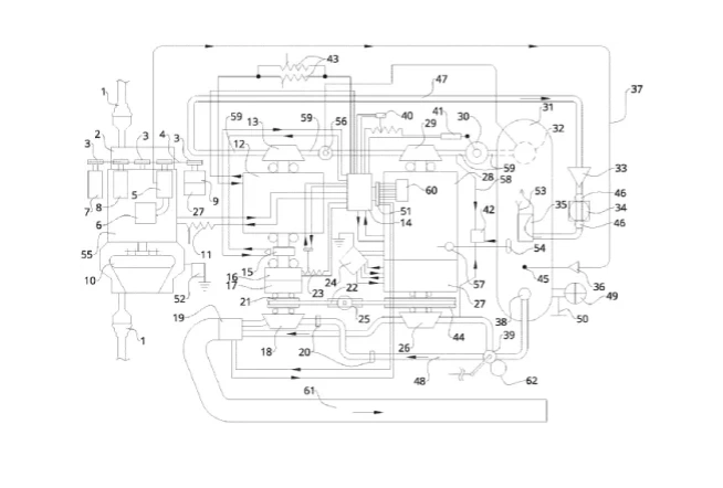
Perpetual Motion Automotive Motor ( A "zero emission vehicle" - No Battery Required!)
In the years and decades to come oil will become exceedingly expensive as the oil was not grown for industrial use but rather harvested from earth's deposits. The following design system is a "draft accelerator" perpetual motion "Active" electric power plant using two types of pressure to then "continually" produce electricity for an electric automobile. The system uses hydraulic fluid ( silicone oil ) and pneumatic ( "air" ) pressure to motivate the power plant. It is important to understand the system does not burn the oil. The system replaces the air pressure automatically.
So many automobile manufacturing companies have built into their business model a less refined product for more money. Correct engineering also accommodates ease of maintenance . What we've been sold is residual payment and an inclined cost of repair upon out dated technology. Sometimes superior engineering is more simple. Old systems are failing and so many corners are cut in the scope of the total process involving compromising safety for increased miles per gallon effecting so many. We are here to alter it. These design alter the public's "work equity" $ "burn" as gasoline... by implementing fuel less electricity for an electric car at an affordable cost to the general public. Function not flash...
The design being a zero emission vehicle then, by it's use, will correct the CO2 (carbon dioxide), / Global Warming / Climate Change problem produced from fossil fuels in multiple ways. The above design will also be able assist in clean air processing of internal combustion engine systems speeding the environmental clean up... until conversion to these type of systems becomes the predominant vehicle motor platform.
Parts List
1. Drive shaft cup
2. Automotive automatic transmission rotated by number 55
3. Pulley and drive belt system causes rotation for numbers 5, 7 ,8, 9, rotational input torque by
pulley upon extending drive shaft from number 55 tandem rotation with the armature of number 55.
4. Drive belt
5. Air pump ( contains electric clutch)
6. Air filter
7. Power steering pump / and power break pump ( a dual pump component ) with unit failure
crossover plumbing and fault indicator sensor to illuminate upon the dash board warning the driver of
low fluid in either of the pumps
8. Air conditioner compressor ( contains electric clutch)
9. 12v alternator
10. Torque converter
11. A "throttle ( potentiometer / variable resistor ( dual coil spring retention to the zero out put electricity
position) operates in tandem with number 43.
12. Electric motor ( "advancer electric motor" ) - electrical power to the unit compensates for the inclined
resistance encountered by the magnetic field within the main high voltage generator when increased
vehicle speed is incurred by the electrification of number 55 ( electrical load compensating / "makes the
generator "baug" resistant").
The applied magnetic pressure from the electric motor, number 12, is then causing advancement of the
system, factored atop the drive belt pulley incline and "hydraulic draft" ( fluid suction ) compounding
oil velocity rate. The oil pressure traversing across the hydraulic impeller causes higher rotation in the
oil pump.
The electric "advancer motor", number 12, would then effectively produce higher
motor rotation capacity than a 10 Hp electric motor. The "counter tilted" gear incline ( ratio gear set
and drive belt and pulley drive system), effectively is then increasing the rotational rate (r.p.m.) of the
motor then advancing the "launch" point of "magnetic pressure" causing increased electric motor speed
at the Hp rating.
13. Hydraulic pump
14. Logic processing "systems mapping" electronic system speed control electronic circuit "box" contains
water inundation "all stop" cut off safety switch sensor so that if the car encounters high water
the generator will shut off.
15. R.P.M. sensor ( revolutions per minute sensor)
16. A "counter tilt" electric motor tandem rotating with the high side of the ratio gear set number 17. Counter
acts upon the gear set's mechanical resistance. The unit also containing an electrical "drag" function
used when shutting off the system to act as an electromagnetic field break system to then slow the
total assemblies rotation down.
17. Ratio gear set ratio at 1:10 input rotation tandem rotated by number 18's internal pneumatic
impeller "wheel" and pulley, number 21 union tandem via drive shaft. The ratio gear set's out put
rotation tandem with number 16's armature that also is tandem with armature of number 12 and
the hydraulic pump internal "pump wheel" of the hydraulic pump, number 13.
18. Pneumatic impeller ( piston type impeller ) "rotary type" impeller contains electric clutch hydraulic
locking to then position the clutch in disengaged or engaged position. The internal clutch system
then actuated "throw out" type weighted pressure plate and secured via a "lock out" solenoid. The
solenoid is connected via wire to the systems logic processing system / mapping control
electronics, number 14 via multi wire connector 51, to then cause automatic functioning of the clutch.
The internal clutch will then be in the engaged position at "Start Up" and dis-engaged position when
the system is in the "run" mode. The clutch system upon shutting the total system down, will then
be returned to the engaged position for subsequent system "re-start".
19. Exhaust air filter ( may be augmented with a electric resistance heating element to then activate
a catalytic converter to process other peoples internal combustion engine automotive exhaust)
20. Pneumatic flow pipe coupling
21. Pulley 4" dia ( diameter)
22. Drive belt
23. Counter tilt electric motor variable resistor / circuit controlled potentiometer
24. Voltage regulator
25. Tension pulley ( adjust the drive belt tension) 3"dia ( diameter)
26. Pneumatic impeller ( centrifugal type ) also acts as an air pump when the air pressure from
the dual component pressure tank is shut off then pulling external "air" from the environment via base
intake air filter upon number 39.
27. Magneto - generator p.m. permanent magnet generator - feeds electricity to the stator / field coil
of number 28- Contains "roller wheel contact brushes"- internal commutator
28. Main high voltage generator contains roller "wheel brushes" redundant off set failure rate indicates upon
the car's dashboard when failure has occurred of if a fault is detected... ie... if the current transmission
has encountered failure. The contact "brush" roller wheel brushes, are then of high hardness with
sealed lubricated bearings
29. Hydraulic impeller "rotates by the hydraulic draft effect of a pneumatically pressurized oil" and causes
the generator armature and magneto's armature to rotate by hydraulic suction and by pneumatically
pressurized oil . The hydraulic impeller is connected, via drive shaft, to the armature of the generator
and commutator within, number 28, and magneto's armature / commutator, number 27. The hydraulic
impeller is also rotating, via internal drive shaft , the large pulley, number 44 and number 26's internal
pneumatic impeller "wheel".
30. Oil flow rate regulator valve - redundant solenoid control - coil spring dampener "opens" under (by) high
suction - solenoid "pushes" the valve closed "restricts" oil flow. The valves inner "tumbler" then allowing
interval / gradian of oil flow does not completely close
31. Dual component pressure storage tank non flammable non electrically conductive hydraulic oil
under pneumatic ( air ) pressure.. air pressure causes oil pressure
32. Oil drain
33. One way valve ( oil / hydraulic fluid )
34. Oil filter ( diaphragm type) so that the oil is directed thru the filter for the first ten seconds of oil flow
when starting the system then the coil spring tension valve plate diaphragm will open due to oil
pressure and velocity of oil then allowing the diaphragm plate to open flow of oil not to then be
encumbered by the oil filter.
35. Oil return coupling
36. One way valve ( pneumatic ) air pressure re-pressurization flow tube
37. Pneumatic pressure pipe / tubing / hose
38. Pneumatic fitting
39. Pneumatic "Start valve" ( is also a "breather valve" so that when the system is in the "run" mode the air
from the combined component pressure storage tank is then shut off and the valve "breathes" via an
air intake air filter retained upon it's base.
40. Circuit controlled variable resistor / circuit controlled potentiometer
41. Solenoid
42. Plasma box ( controls and dissipates unwanted system static electricity / static electricity control
acts as an electricity electrical ground)
43. Potentiometer / variable resistor ( may work in unison with the system "throttle", number 11, to then
cause "baug" resistant power ban incline)
44. Large pulley 12"dia (diameter)
45. Pneumatic return coupling / pipe fitting
46. Flow system shut off valve
47. Oil flow pipe
48. Pneumatic high pressure flow pipe / pressure hose
49. Over pressure max pressure system safety valve ( vents pneumatic over pressure) - contains one
way manual pneumatic fill valve ( allows for manual pneumatic pressurization for initial
start up / operating pneumatic pressure)
50. Pneumatic pressure sensor controls air "re-pack" air pump number 5, to keep the pneumatic pressure
full in the dual component pressure storage tank
51. Multi wire "ribbon wire" bus connector wire connector instrumentation wire connector
52. Plasma box (controls and dissipates unwanted system static electricity / static electricity control
acts as an electricity electrical ground)
53. Manual pneumatic fill valve one way fill valve
54. Oil fill pressure cap with wire security retainer clip . The threaded screw on cap then is also with a
pneumatic "decompression" valve used when changing the pressure tank's oil. The pressure rated screw
cap also contains a redundant over pressure pneumatic pressure safety valve then rated at the system
operating pneumatic pressure to allow for decompressing of pneumatic pressure (vents "over pressure").
55. Main electric automotive motor (rotates the torque converter and automatic automotive transmission)
56. oil inlet safety valve / coil spring run away effect prevention dampener valve (insures the
structural integrity of the flow pipe), and flow cycle "electric actuation valve", that then regulates
the available oil to the hydraulic pump, number 13. This then is able to "control" the system
speed by direction of oil pressure then by-passing the hydraulic draft impeller, number 29. The logic
circuit board then uses the r.p.m. sensor information to set the valve position via electronic
solenoid to cause the system "run" settings to operate correctly...
The "electric valve assembly" flow valve then retained by internal coil spring to the oil
flow "by-pass position" to allow valve failure to then default to the "open flow" position "by-passing" the
hydraulic impeller, number 29.
This is a critical safety feature!
Electrification of the said valve then having increment "adjustable current level" and oil
pressure / volume flow variance, then determined to obtain system speed, "base idle", referencing the drive
line's assemblies r.p.m. sensor then extrapolating the current level required by the electronic circuits
within number 14.
Description
The design, then only displacing pneumatic pressure at "Start Up" with the ability to replace the air pressure automatically. The air pressure is replaced by the systems "on-board" air pump. The design cycles hydraulic pressure to produce electricity. It does not burn the oil. The "working fluid" then a "non electrically conductive" - "non flammable oil" being Siloxane ( silicone oil ).
The design then will allow for an unlimited range electric vehicle with "on demand" service
(* no battery required ! ).
Since this electric car requires no battery the manufacturing cost is then lowered thus reducing the final retail cost of the product or allowing for more crash safety at comparable cost making the final product a more attractive purchase.
The above design system is an "Active" electrical generator (an A.E.G. motor) automotive motor platform that allows for unlimited range on-demand service 24/7. The design uses sealed generator / magneto and motor system to then control low level Ozone. The system uses a drive belt, number 22 but may be made with a vented, "oil encased" lubrication system with a chain and sprocket system to then last a bit longer the pulley numbers 21, 25, and number 44 would then become sprockets and number 22 would then become a drive chain within a vented oil lubricated encasement with threaded magnetic drain plug.
The design system only dissipates the pneumatic pressure at "Start Up". ( ie... the discharge of air pressure from the dual component pressure storage tank). When the design is in the run "mode" the air pressure from the combined component pressure storage tank is shut off. This reduces fatigue upon the systems air pump only working for a short time to replenish the air pressure in the dual component pressure storage tank, number 31.
When number 13, hydraulic pump, is at high velocity the oil traversing across number 29 is then causing the main high voltage generator to then accelerate. The large pulley, number 44, then in tandem rotation with the hydraulic impeller, number 29, so that the receiving pulley, number 21, is then at greater rate of rotation creating a compound incline in rate of rotation.
The basal ( base ) pneumatic pressure within the combined component / dual component pressure storage tank, number 31, is then greater slightly to include the required "start pneumatic pressure displacement" requirement added to the generators "run" p.s.i. (pounds per square inch), pressure requirement. The "run" p.s.i. then maintained by the air pressure sensor referencing the dual component air pressure within number 31 then actuating, via electronic circuit, the electric clutch in the system air pump number 5.
When the oil is returning to the combined component pressure storage tank, the return coupling is then atop the pressure tank so that the oil is injecting into the decreasing pneumatic pressure. The oil returns faster than the discharge due to the oil being displaced unto the hydraulic impeller with the velocity increased by the hydraulic pump. The return of oil at greater rate then will increase the pneumatic pressure allowing for a greater oil pressure displacement pressure and provide more "work" capacity as the system speeds up..
It is important to understand this works due to the "states" of matter. Air pressure "flexes" and hydraulic oil acts as a "solid". In addition the "draft effect" is incurred using a "suction effect" ie... "pulling" hydraulic fluid in confinement to then incur a system speed incline in tandem with a "counter tilted" speed incline gear set while advancing the application point of magnetic "pressure" via electric motor to then have the
magnetic "pressure" ( electricity inducing magnetism ) then to cause the horse power of the electric motor applied atop the fluid velocity rate.
The dual component pressure tank, number 31 ( air pressure atop oil causing oil pressure ) pressure tank then will only allow safe levels of pneumatic pressure as the max pressure safety vent will then allow for decompression of pneumatic pressure should the level become to high. The over pressure / max pressure safety valve, number 49, will also include a fault sensor to indicate that the valve is working correctly.. a critical component such as this will also require a safety circuit to then cause a system "all stop" function should
it ( safety valve, number 49 ), become encumbered. The "all stop" function then will close the valve, number 30 and reduce the electricity feed current to the potentiometer, number 23, via electric circuit.
The magneto then energizes the stator / field coil of the generator post voltage regulator to then produce electricity by the hydraulic pump implementing the draft effect. ( ie... pulling pressurized oil in confinement - "within the pipe" ), This allows valve number 30 to open producing a syringe effect drafting pressurized fluid across the hydraulic impeller, number 29, by the hydraulic pump, number 13, to accelerate the generator assembly while the drive belt side of the system then also advances the hydraulic pump to greater rotational rate upon the adjacent assembly causing the "work transference fluid" (silicone oil) to then return to the dual component pressure storage tank faster than the hydraulic fluid (silicone oil) is discharged. This produces constant motion and sustained electricity production.
The "counter tilt" electric motor, number 16, then "zero's" the resistance in the ratio gear set, to then, with the counter tilt electric motor energized, cause a system speed incline and stable "idle" also causing the hydraulic pump to advance at greater rate. This allows for a percentile of the generated electricity to be reintroduced to the "counter tilt" electric motor ( ie... from the generator number 28 to number 16 and number 12 ), to cause sufficient levels of rotation for the generator's remainder out put electricity to electrify the main electric motor, number 55, that propels the automobile via automotive automatic transmission.
The electricity producing power plant is electrically insulated from the chassis and it's final encasement can be made water proof ( requires additional cooling coil from the car's air conditioning system inert sealed gas filled chamber - zero water vapor in system ) so that even if encountering high flood the system will remain dry within the design encasement with the cooling coils then cooling the power system ( electric motors and generators).
If a vented version of the final encasement is used the system will be able to heat dissipate by electric blower fan & thermostat, but be a water safe design so that even if submerged in water the system will not cause the water conductive electrically. The generator system and electric motor drive system final casing is then also with an inductance cage to prevent internal or external disruption by electro-magentic pulse ( e.m.p. ). The inductance cage shields sensitive electronics.
The automotive automatic transmission is also electrically insulated from the main electric drive motor.. The system uses non electrically conductive motor mounts for the generator system and the electric motor automotive automatic transmission system. The drive shafts also contain a electricity insulator coupler to then prevent any stray electricity from reaching the drive shaft's exposed drive shaft cup.
The main electric motor, power plant ( generator), and automotive transmission system are not electrically grounded to the chassis. There are two "plasma box" to harvest "recycle" any static electricity produced from the flow of pneumatic displacement or the motion of hydraulic oil ( silicone oil ) the plasma box then acting as an electrical ground also reporting to the system mapping electronics / control circuits, number 14. The plasma box is an "artificial electrical ground" that must dissipate any electrical inductance to prevent any electrical shock hazard.
* Note - The circles upon the drive shaft, connecting components, then represent sealed lubricated
bearings that stabilize the drive shaft's rotation.
* Note - Air pressure hose - flow tube / pipe terminal ends are then connected to the system
valve / components with pressure rated couplings to then also assist in drive belt change
ease of access. The oil piping flow system uses pressure rated metal pipe of stainless steel
and the pneumatic hoses may be of pressure rated plastic or flex hose.
Stain less steel will also be the material selection of choice for all rotating high speed components
to reduce the chance of failure incident due to rust. High speed components then contained within
a shock casing to then mitigate the chance of manufacturing defect causing a projectile
hazard.
All pressure fittings that join the flow pipes or connection pressure hoses then of stainless
steel also. The flow pipes are then electrically insulated upon the exterior of the pipe and encased
in a "shock casing" ( impact shield ) to reduce chance of injury should the pipe become damaged
or fails due to manufacturing defect.
* Note - The system is able to scale according to the application then serving is unique function so the ratings for different applications regarding Hp
( horse power ) and electricity production out put, will also then be adjusted in accordance. An electric automobile then requiring an electric drive
motor (number 55), of about 60 Hp and a generating capacity of 80Kw for a system such as this will allow the electric motors upon the high side of the ratio gear then to both be rated at 10 hp equivalent.
This website uses cookies.
We use cookies to analyze website traffic and optimize your website experience. By accepting our use of cookies, your data will be aggregated with all other user data.